Note
Go to the end to download the full example code.
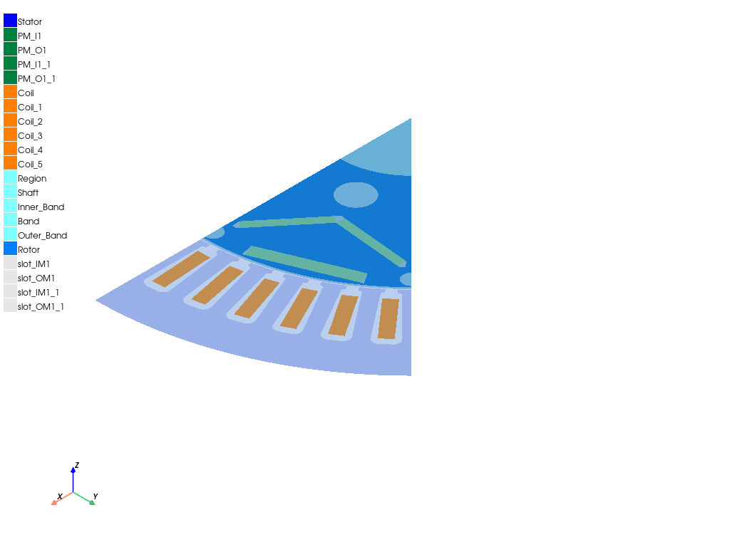
Maxwell 2D: PM synchronous motor transient analysis#
This example shows how you can use PyAEDT to create a Maxwell 2D transient analysis for an interior permanent magnet electric motor.
Perform required imports#
Perform required imports.
from math import sqrt as mysqrt

import csv
import os
import pyaedt
Set AEDT version#
Set AEDT version.
aedt_version = "2024.1"
Initialize Maxwell 2D#
Initialize Maxwell 2D, providing the version, path to the project, and the design name and type.
setup_name = "MySetupAuto"
solver = "TransientXY"

project_name = pyaedt.generate_unique_project_name()
design_name = "Sinusoidal"
Initialize definitions for stator, rotor, and shaft#
Initialize geometry parameter definitions for the stator, rotor, and shaft. The naming refers to RMxprt primitives.
geom_params = {
    "DiaGap": "132mm",
    "DiaStatorYoke": "198mm",
    "DiaStatorInner": "132mm",
    "DiaRotorLam": "130mm",
    "DiaShaft": "44.45mm",
    "DiaOuter": "198mm",
    "Airgap": "1mm",
    "SlotNumber": "48",
    "SlotType": "3"
}
Initialize definitions for stator windings#
Initialize geometry parameter definitions for the stator windings. The naming refers to RMxprt primitives.
wind_params = {
    "Layers": "1",
    "ParallelPaths": "2",
    "R_Phase": "7.5mOhm",
    "WdgExt_F": "5mm",
    "SpanExt": "30mm",
    "SegAngle": "0.25",
    "CoilPitch": "5",  # coil pitch in slots
    "Coil_SetBack": "3.605732823mm",
    "SlotWidth": "2.814mm",  # RMxprt Bs0
    "Coil_Edge_Short": "3.769235435mm",
    "Coil_Edge_Long": "15.37828521mm"
}
Initialize definitions for model setup#
Initialize geometry parameter definitions for the model setup.
mod_params = {
    "NumPoles": "8",
    "Model_Length": "80mm",
    "SymmetryFactor": "8",
    "Magnetic_Axial_Length": "150mm",
    "Stator_Lam_Length": "0mm",
    "StatorSkewAngle": "0deg",
    "NumTorquePointsPerCycle": "30",
    "mapping_angle": "0.125*4deg",
    "num_m": "16",
    "Section_Angle": "360deg/SymmetryFactor"
}
Initialize definitions for operational machine#
Initialize geometry parameter definitions for the operational machine. This identifies the operating point for the transient setup.
oper_params = {
    "InitialPositionMD": "180deg/4",
    "IPeak": "480A",
    "MachineRPM": "3000rpm",
    "ElectricFrequency": "MachineRPM/60rpm*NumPoles/2*1Hz",
    "ElectricPeriod": "1/ElectricFrequency",
    "BandTicksinModel": "360deg/NumPoles/mapping_angle",
    "TimeStep": "ElectricPeriod/(2*BandTicksinModel)",
    "StopTime": "ElectricPeriod",
    "Theta_i": "135deg"
}
Set non-graphical mode#
Set non-graphical mode. "PYAEDT_NON_GRAPHICAL" is needed to
generate documentation only.
You can set non_graphical either to True or False.
non_graphical = False
Launch Maxwell 2D#
Launch Maxwell 2D and save the project.
M2D = pyaedt.Maxwell2d(project=project_name,
                       version=aedt_version,
                       design=design_name,
                       solution_type=solver,
                       new_desktop=True,
                       non_graphical=non_graphical
                       )
C:\actions-runner\_work\_tool\Python\3.10.9\x64\lib\subprocess.py:1072: ResourceWarning: subprocess 10100 is still running
  _warn("subprocess %s is still running" % self.pid,
C:\actions-runner\_work\pyaedt\pyaedt\.venv\lib\site-packages\pyaedt\generic\settings.py:428: ResourceWarning: unclosed file <_io.TextIOWrapper name='D:\\Temp\\pyaedt_ansys.log' mode='a' encoding='cp1252'>
  self._logger = val
Create object to access 2D modeler#
Create the object mod2D to access the 2D modeler easily.
mod2D = M2D.modeler
mod2D.delete()
mod2D.model_units = "mm"
Define variables from dictionaries#
Define design variables from the created dictionaries.
for k, v in geom_params.items():
    M2D[k] = v
for k, v in wind_params.items():
    M2D[k] = v
for k, v in mod_params.items():
    M2D[k] = v
for k, v in oper_params.items():
    M2D[k] = v
Define path for non-linear material properties#
Define the path for non-linear material properties. Materials are stored in text files.
filename_lam, filename_PM = pyaedt.downloads.download_leaf()
Create first material#
Create the material "Copper (Annealed)_65C".
mat_coils = M2D.materials.add_material("Copper (Annealed)_65C")
mat_coils.update()
mat_coils.conductivity = "49288048.9198"
mat_coils.permeability = "1"
Create second material#
Create the material "Arnold_Magnetics_N30UH_80C".
The BH curve is read from a tabbed CSV file, and a list (BH_List_PM)
is created. This list is passed to the mat_PM.permeability.value
method.
mat_PM = M2D.materials.add_material("Arnold_Magnetics_N30UH_80C_new")
mat_PM.update()
mat_PM.conductivity = "555555.5556"
mat_PM.set_magnetic_coercivity(value=-800146.66287534, x=1, y=0, z=0)
mat_PM.mass_density = "7500"
BH_List_PM = []
with open(filename_PM) as f:
    reader = csv.reader(f, delimiter='\t')
    next(reader)
    for row in reader:
        BH_List_PM.append([float(row[0]), float(row[1])])
mat_PM.permeability.value = BH_List_PM
Create third material#
Create the laminated material 30DH_20C_smooth.
This material has a BH curve and a core loss model,
which is set to electrical steel.
mat_lam = M2D.materials.add_material("30DH_20C_smooth")
mat_lam.update()
mat_lam.conductivity = "1694915.25424"
kh = 71.7180985413
kc = 0.25092214579
ke = 12.1625774023
kdc = 0.001
eq_depth = 0.001
mat_lam.set_electrical_steel_coreloss(kh, kc, ke, kdc, eq_depth)
mat_lam.mass_density = "7650"
BH_List_lam = []
with open(filename_lam) as f:
    reader = csv.reader(f, delimiter='\t')
    next(reader)
    for row in reader:
        BH_List_lam.append([float(row[0]), float(row[1])])
mat_lam.permeability.value = BH_List_lam
Create geometry for stator#
Create the geometry for the stator. It is created via the RMxprt user-defined primitive. A list of lists is created with the proper UDP parameters.
udp_par_list_stator = [["DiaGap", "DiaGap"], ["DiaYoke", "DiaStatorYoke"], ["Length", "Stator_Lam_Length"],
                       ["Skew", "StatorSkewAngle"], ["Slots", "SlotNumber"], ["SlotType", "SlotType"],
                       ["Hs0", "1.2mm"], ["Hs01", "0mm"], ["Hs1", "0.4834227384999mm"],
                       ["Hs2", "17.287669825502mm"],
                       ["Bs0", "2.814mm"], ["Bs1", "4.71154109036mm"], ["Bs2", "6.9777285790998mm"], ["Rs", "2mm"],
                       ["FilletType", "1"], ["HalfSlot", "0"], ["VentHoles", "0"], ["HoleDiaIn", "0mm"],
                       ["HoleDiaOut", "0mm"],
                       ["HoleLocIn", "0mm"], ["HoleLocOut", "0mm"], ["VentDucts", "0"], ["DuctWidth", "0mm"],
                       ["DuctPitch", "0mm"],
                       ["SegAngle", "0deg"], ["LenRegion", "Model_Length"], ["InfoCore", "0"]]

stator_id = mod2D.create_udp(dll="RMxprt/VentSlotCore.dll", parameters=udp_par_list_stator, library='syslib',
                             name='my_stator')  # name not taken
Assign properties to stator#
Assign properties to the stator. The following code assigns
the material, name, color, and solve_inside properties.
M2D.assign_material(assignment=stator_id, material="30DH_20C_smooth")
stator_id.name = "Stator"
stator_id.color = (0, 0, 255)  # rgb
stator_id.solve_inside = True  # to be reassigned: M2D.assign material puts False if not dielectric
Create geometry for PMs#
Create the geometry for the PMs (permanent magnets). In Maxwell 2D, you assign
magnetization via the coordinate system. Because each PM needs to have a coordinate
system in the face center, auxiliary functions are created. Here, you use the auxiliary
function find_elements(lst1, lst2) to find the elements in list lst1 with indexes
in list lst2.
def find_elements(lst1, lst2):
    return [lst1[i] for i in lst2]
Find largest elements in list#
Use the auxiliary function find_n_largest (input_len_list, n_largest_edges)
to find the n largest elements in the list input_len_list.
def find_n_largest(input_len_list, n_largest_edges):
    tmp = list(input_len_list)
    copied = list(input_len_list)
    copied.sort()  # sort list so that largest elements are on the far right
    index_list = []
    for n in range(1, n_largest_edges + 1):  # get index of the nth largest element
        index_list.append(tmp.index(copied[-n]))
        tmp[tmp.index(copied[-n])] = 0  # index can only get the first occurrence that solves the problem
    return index_list
Create coordinate system for PMs#
Create the coordinate system for the PMs. The inputs are the object name, coordinate system name, and inner or outer magnetization. Find the two longest edges of the magnets and get the midpoint of the outer edge. You must have this point to create the face coordinate systems in case of outer magnetization.
def create_cs_magnets(pm_id, cs_name, point_direction):
    pm_face_id = mod2D.get_object_faces(pm_id.name)[0]  # works with name only
    pm_edges = mod2D.get_object_edges(pm_id.name)  # gets the edges of the PM object
    edge_len_list = list(
        map(mod2D.get_edge_length, pm_edges))  # apply method get_edge_length to all elements of list pm_edges
    index_2_longest = find_n_largest(edge_len_list, 2)  # find the 2 longest edges of the PM
    longest_edge_list = find_elements(pm_edges, index_2_longest)
    edge_center_list = list(map(mod2D.get_edge_midpoint,
                                longest_edge_list))  # apply method get_edge_midpoint to all elements of list longest_edge_list

    rad = lambda x: mysqrt(x[0] * x[0] + x[1] * x[1] + x[2] * x[2])
    index_largest_r = find_n_largest(list(map(rad, edge_center_list)), 2)
    longest_edge_list2 = [longest_edge_list[i] for i in index_largest_r]  # reorder: outer first element of the list
    if point_direction == 'outer':
        my_axis_pos = longest_edge_list2[0]
    elif point_direction == 'inner':
        my_axis_pos = longest_edge_list2[1]

    mod2D.create_face_coordinate_system(face=pm_face_id, origin=pm_face_id, axis_position=my_axis_pos,
                                        axis="X", name=cs_name)
    pm_id.part_coordinate_system = cs_name
    mod2D.set_working_coordinate_system('Global')
Create outer and inner PMs#
Create the outer and inner PMs and assign color to them.
IM1_points = [[56.70957112, 3.104886585, 0], [40.25081875, 16.67243502, 0], [38.59701538, 14.66621111, 0],
              [55.05576774, 1.098662669, 0]]
OM1_points = [[54.37758185, 22.52393189, 0], [59.69688156, 9.68200639, 0], [63.26490432, 11.15992981, 0],
              [57.94560461, 24.00185531, 0]]
IPM1_id = mod2D.create_polyline(points=IM1_points, cover_surface=True, name="PM_I1",
                                material="Arnold_Magnetics_N30UH_80C_new")
IPM1_id.color = (0, 128, 64)
OPM1_id = mod2D.create_polyline(points=OM1_points, cover_surface=True, name="PM_O1",
                                material="Arnold_Magnetics_N30UH_80C_new")
OPM1_id.color = (0, 128, 64)
Create coordinate system for PMs in face center#
Create the coordinate system for PMs in the face center.
create_cs_magnets(IPM1_id, 'CS_' + IPM1_id.name, 'outer')
create_cs_magnets(OPM1_id, 'CS_' + OPM1_id.name, 'outer')
Duplicate and mirror PMs#
Duplicate and mirror the PMs along with the local coordinate system.
mod2D.duplicate_and_mirror([IPM1_id, OPM1_id], origin=[0, 0, 0],
                           vector=["cos((360deg/SymmetryFactor/2)+90deg)", "sin((360deg/SymmetryFactor/2)+90deg)", 0])
id_PMs = mod2D.get_objects_w_string("PM", case_sensitive=True)
Create coils#
Create the coils.
coil_id = mod2D.create_rectangle(origin=['DiaRotorLam/2+Airgap+Coil_SetBack', '-Coil_Edge_Short/2', 0],
                                 sizes=['Coil_Edge_Long', 'Coil_Edge_Short', 0],
                                 name='Coil', material="Copper (Annealed)_65C")
coil_id.color = (255, 128, 0)
M2D.modeler.rotate(assignment=coil_id, axis="Z", angle="360deg/SlotNumber/2")
coil_id.duplicate_around_axis(axis="Z", angle="360deg/SlotNumber", nclones='CoilPitch+1',
                              create_new_objects=True)
id_coils = mod2D.get_objects_w_string("Coil", case_sensitive=True)
Create shaft and region#
Create the shaft and region.
region_id = mod2D.create_circle(position=[0, 0, 0], radius='DiaOuter/2',
                                num_sides='SegAngle', is_covered=True, name='Region')
shaft_id = mod2D.create_circle(position=[0, 0, 0], radius='DiaShaft/2',
                               num_sides='SegAngle', is_covered=True, name='Shaft')
Create bands#
Create the inner band, band, and outer band.
bandIN_id = mod2D.create_circle(position=[0, 0, 0], radius='(DiaGap - (1.5 * Airgap))/2',
                                num_sides='mapping_angle', is_covered=True, name='Inner_Band')
bandMID_id = mod2D.create_circle(position=[0, 0, 0], radius='(DiaGap - (1.0 * Airgap))/2',
                                 num_sides='mapping_angle', is_covered=True, name='Band')
bandOUT_id = mod2D.create_circle(position=[0, 0, 0], radius='(DiaGap - (0.5 * Airgap))/2',
                                 num_sides='mapping_angle', is_covered=True, name='Outer_Band')
Assign motion setup to object#
Assign a motion setup to a Band object named RotatingBand_mid.
M2D.assign_rotate_motion(assignment='Band', coordinate_system="Global", axis="Z", positive_movement=True,
                         start_position="InitialPositionMD", angular_velocity="MachineRPM")
<pyaedt.modules.Boundary.BoundaryObject object at 0x00000187E78ABAC0>
Create list of vacuum objects#
Create a list of vacuum objects and assign color.
vacuum_obj_id = [shaft_id, region_id, bandIN_id, bandMID_id, bandOUT_id]  # put shaft first
for item in vacuum_obj_id:
    item.color = (128, 255, 255)
Create rotor#
Create the rotor. Holes are specific to the lamination. Allocated PMs are created.
rotor_id = mod2D.create_circle(position=[0, 0, 0], radius='DiaRotorLam/2',
                               num_sides=0, name="Rotor", material="30DH_20C_smooth")
rotor_id.color = (0, 128, 255)
mod2D.subtract(rotor_id, shaft_id, keep_originals=True)
void_small_1_id = mod2D.create_circle(position=[62, 0, 0], radius="2.55mm",
                                      num_sides=0, name="void1", material="vacuum")
M2D.modeler.duplicate_around_axis(void_small_1_id, axis="Z", angle="360deg/SymmetryFactor",
                                  clones=2, create_new_objects=False)
void_big_1_id = mod2D.create_circle(position=[29.5643, 12.234389332712, 0], radius='9.88mm/2',
                                    num_sides=0, name="void_big", material="vacuum")
mod2D.subtract(rotor_id, [void_small_1_id, void_big_1_id], keep_originals=False)

slot_IM1_points = [[37.5302872, 15.54555396, 0], [55.05576774, 1.098662669, 0], [57.33637589, 1.25, 0],
                   [57.28982158, 2.626565019, 0], [40.25081875, 16.67243502, 0]]
slot_OM1_points = [[54.37758185, 22.52393189, 0], [59.69688156, 9.68200639, 0], [63.53825619, 10.5, 0],
                   [57.94560461, 24.00185531, 0]]
slot_IM_id = mod2D.create_polyline(points=slot_IM1_points, cover_surface=True, name="slot_IM1", material="vacuum")
slot_OM_id = mod2D.create_polyline(points=slot_OM1_points, cover_surface=True, name="slot_OM1", material="vacuum")

M2D.modeler.duplicate_and_mirror(assignment=[slot_IM_id, slot_OM_id], origin=[0, 0, 0],
                                 vector=["cos((360deg/SymmetryFactor/2)+90deg)",
                                         "sin((360deg/SymmetryFactor/2)+90deg)", 0])

id_holes = mod2D.get_objects_w_string("slot_", case_sensitive=True)
M2D.modeler.subtract(rotor_id, id_holes, keep_originals=True)
True
Create section of machine#
Create a section of the machine. This allows you to take advantage of symmetries.
object_list = [stator_id, rotor_id] + vacuum_obj_id
mod2D.create_coordinate_system(origin=[0, 0, 0],
                               reference_cs="Global",
                               name="Section",
                               mode="axis",
                               x_pointing=["cos(360deg/SymmetryFactor)", "sin(360deg/SymmetryFactor)", 0],
                               y_pointing=["-sin(360deg/SymmetryFactor)", "cos(360deg/SymmetryFactor)", 0])

mod2D.set_working_coordinate_system("Section")
mod2D.split(object_list, "ZX", sides="NegativeOnly")
mod2D.set_working_coordinate_system("Global")
mod2D.split(object_list, "ZX", sides="PositiveOnly")
['Stator,Rotor,Shaft,Region,Inner_Band,Band,Outer_Band']
Create boundary conditions#
Create independent and dependent boundary conditions. Edges for assignment are picked by position. The points for edge picking are in the airgap.
pos_1 = "((DiaGap - (1.0 * Airgap))/4)"
id_bc_1 = mod2D.get_edgeid_from_position(position=[pos_1, 0, 0], assignment='Region')
id_bc_2 = mod2D.get_edgeid_from_position(
    position=[pos_1 + "*cos((360deg/SymmetryFactor))", pos_1 + "*sin((360deg/SymmetryFactor))", 0], assignment='Region')
M2D.assign_master_slave(independent=id_bc_1, dependent=id_bc_2, reverse_master=False, reverse_slave=True,
                        same_as_master=False, boundary="Matching")
(<pyaedt.modules.Boundary.BoundaryObject object at 0x0000018804C241C0>, <pyaedt.modules.Boundary.BoundaryObject object at 0x0000018804C259C0>)
Assign vector potential#
Assign a vector potential of 0 to the second position.
<pyaedt.modules.Boundary.BoundaryObject object at 0x0000018804C25B40>
Create excitations#
Create excitations, defining phase currents for the windings.
PhA_current = "IPeak * cos(2*pi*ElectricFrequency*time+Theta_i)"
PhB_current = "IPeak * cos(2*pi * ElectricFrequency*time - 120deg+Theta_i)"
PhC_current = "IPeak * cos(2*pi * ElectricFrequency*time - 240deg+Theta_i)"
Define windings in phase A#
Define windings in phase A.
M2D.assign_coil(assignment=["Coil"], conductors_number=6, polarity="Positive", name="CT_Ph1_P2_C1_Go")
M2D.assign_coil(assignment=["Coil_5"], conductors_number=6, polarity="Negative", name="CT_Ph1_P2_C1_Ret")
M2D.assign_winding(assignment=None, winding_type="Current", is_solid=False, current=PhA_current, parallel_branches=1,
                   name="Phase_A")
M2D.add_winding_coils(assignment="Phase_A", coils=["CT_Ph1_P2_C1_Go", "CT_Ph1_P2_C1_Ret"])
True
Define windings in phase B#
Define windings in phase B.
M2D.assign_coil(assignment="Coil_3", conductors_number=6, polarity="Positive", name="CT_Ph3_P1_C2_Go")
M2D.assign_coil(assignment="Coil_4", conductors_number=6, polarity="Positive", name="CT_Ph3_P1_C1_Go")
M2D.assign_winding(assignment=None, winding_type="Current", is_solid=False, current=PhB_current, parallel_branches=1,
                   name="Phase_B")
M2D.add_winding_coils(assignment="Phase_B", coils=["CT_Ph3_P1_C2_Go", "CT_Ph3_P1_C1_Go"])
True
Define windings in phase C#
Define windings in phase C.
M2D.assign_coil(assignment="Coil_1", conductors_number=6, polarity="Negative", name="CT_Ph2_P2_C2_Ret")
M2D.assign_coil(assignment="Coil_2", conductors_number=6, polarity="Negative", name="CT_Ph2_P2_C1_Ret")
M2D.assign_winding(assignment=None, winding_type="Current", is_solid=False, current=PhC_current, parallel_branches=1,
                   name="Phase_C")
M2D.add_winding_coils(assignment="Phase_C", coils=["CT_Ph2_P2_C2_Ret", "CT_Ph2_P2_C1_Ret"])
True
Assign total current on PMs#
Assign a total current of 0 on the PMs.
Create mesh operations#
Create the mesh operations.
M2D.mesh.assign_length_mesh(id_coils, inside_selection=True, maximum_length=3, maximum_elements=None, name="coils")
M2D.mesh.assign_length_mesh(stator_id, inside_selection=True, maximum_length=3, maximum_elements=None, name="stator")
M2D.mesh.assign_length_mesh(rotor_id, inside_selection=True, maximum_length=3, maximum_elements=None, name="rotor")
<pyaedt.modules.Mesh.MeshOperation object at 0x0000018804C0CCD0>
Turn on eddy effects#
Turn on eddy effects.
# M2D.eddy_effects_on(eddy_effects_list,activate_eddy_effects=True, activate_displacement_current=False)
Turn on core loss#
Turn on core loss.
core_loss_list = ['Rotor', 'Stator']
M2D.set_core_losses(core_loss_list)
True
Compute transient inductance#
Compute the transient inductance.
M2D.change_inductance_computation(compute_transient_inductance=True, incremental_matrix=False)
True
Set model depth#
Set the model depth.
M2D.model_depth = "Magnetic_Axial_Length"
Set symmetry factor#
Set the symmetry factor.
M2D.change_symmetry_multiplier("SymmetryFactor")
True
Create setup and validate#
Create the setup and validate it.
setup = M2D.create_setup(name=setup_name)
setup.props["StopTime"] = "StopTime"
setup.props["TimeStep"] = "TimeStep"
setup.props["SaveFieldsType"] = "None"
setup.props["OutputPerObjectCoreLoss"] = True
setup.props["OutputPerObjectSolidLoss"] = True
setup.props["OutputError"] = True
setup.update()
M2D.validate_simple()

model = M2D.plot(show=False)
model.plot(os.path.join(M2D.working_directory, "Image.jpg"))
True
Initialize definitions for output variables#
Initialize the definitions for the output variables. These will be used later to generate reports.
output_vars = {
    "Current_A": "InputCurrent(Phase_A)",
    "Current_B": "InputCurrent(Phase_B)",
    "Current_C": "InputCurrent(Phase_C)",
    "Flux_A": "FluxLinkage(Phase_A)",
    "Flux_B": "FluxLinkage(Phase_B)",
    "Flux_C": "FluxLinkage(Phase_C)",
    "pos": "(Moving1.Position -InitialPositionMD) *NumPoles/2",
    "cos0": "cos(pos)",
    "cos1": "cos(pos-2*PI/3)",
    "cos2": "cos(pos-4*PI/3)",
    "sin0": "sin(pos)",
    "sin1": "sin(pos-2*PI/3)",
    "sin2": "sin(pos-4*PI/3)",
    "Flux_d": "2/3*(Flux_A*cos0+Flux_B*cos1+Flux_C*cos2)",
    "Flux_q": "-2/3*(Flux_A*sin0+Flux_B*sin1+Flux_C*sin2)",
    "I_d": "2/3*(Current_A*cos0 + Current_B*cos1 + Current_C*cos2)",
    "I_q": "-2/3*(Current_A*sin0 + Current_B*sin1 + Current_C*sin2)",
    "Irms": "sqrt(I_d^2+I_q^2)/sqrt(2)",
    "ArmatureOhmicLoss_DC": "Irms^2*R_phase",
    "Lad": "L(Phase_A,Phase_A)*cos0 + L(Phase_A,Phase_B)*cos1 + L(Phase_A,Phase_C)*cos2",
    "Laq": "L(Phase_A,Phase_A)*sin0 + L(Phase_A,Phase_B)*sin1 + L(Phase_A,Phase_C)*sin2",
    "Lbd": "L(Phase_B,Phase_A)*cos0 + L(Phase_B,Phase_B)*cos1 + L(Phase_B,Phase_C)*cos2",
    "Lbq": "L(Phase_B,Phase_A)*sin0 + L(Phase_B,Phase_B)*sin1 + L(Phase_B,Phase_C)*sin2",
    "Lcd": "L(Phase_C,Phase_A)*cos0 + L(Phase_C,Phase_B)*cos1 + L(Phase_C,Phase_C)*cos2",
    "Lcq": "L(Phase_C,Phase_A)*sin0 + L(Phase_C,Phase_B)*sin1 + L(Phase_C,Phase_C)*sin2",
    "L_d": "(Lad*cos0 + Lbd*cos1 + Lcd*cos2) * 2/3",
    "L_q": "(Laq*sin0 + Lbq*sin1 + Lcq*sin2) * 2/3",
    "OutputPower": "Moving1.Speed*Moving1.Torque",
    "Ui_A": "InducedVoltage(Phase_A)",
    "Ui_B": "InducedVoltage(Phase_B)",
    "Ui_C": "InducedVoltage(Phase_C)",
    "Ui_d": "2/3*(Ui_A*cos0 + Ui_B*cos1 + Ui_C*cos2)",
    "Ui_q": "-2/3*(Ui_A*sin0 + Ui_B*sin1 + Ui_C*sin2)",
    "U_A": "Ui_A+R_Phase*Current_A",
    "U_B": "Ui_B+R_Phase*Current_B",
    "U_C": "Ui_C+R_Phase*Current_C",
    "U_d": "2/3*(U_A*cos0 + U_B*cos1 + U_C*cos2)",
    "U_q": "-2/3*(U_A*sin0 + U_B*sin1 + U_C*sin2)"
}
Create output variables for postprocessing#
Create output variables for postprocessing.
for k, v in output_vars.items():
    M2D.create_output_variable(k, v)
Initialize definition for postprocessing plots#
Initialize the definition for postprocessing plots.
post_params = {
    "Moving1.Torque": "TorquePlots"
}
Initialize definition for postprocessing multiplots#
Initialize the definition for postprocessing multiplots.
post_params_multiplot = {  # reports
    ("U_A", "U_B", "U_C", "Ui_A", "Ui_B", "Ui_C"): "PhaseVoltages",
    ("CoreLoss", "SolidLoss", "ArmatureOhmicLoss_DC"): "Losses",
    ("InputCurrent(Phase_A)", "InputCurrent(Phase_B)", "InputCurrent(Phase_C)"): "PhaseCurrents",
    ("FluxLinkage(Phase_A)", "FluxLinkage(Phase_B)", "FluxLinkage(Phase_C)"): "PhaseFluxes",
    ("I_d", "I_q"): "Currents_dq",
    ("Flux_d", "Flux_q"): "Fluxes_dq",
    ("Ui_d", "Ui_q"): "InducedVoltages_dq",
    ("U_d", "U_q"): "Voltages_dq",
    ("L(Phase_A,Phase_A)", "L(Phase_B,Phase_B)", "L(Phase_C,Phase_C)", "L(Phase_A,Phase_B)", "L(Phase_A,Phase_C)",
     "L(Phase_B,Phase_C)"): "PhaseInductances",
    ("L_d", "L_q"): "Inductances_dq",
    ("CoreLoss", "CoreLoss(Stator)", "CoreLoss(Rotor)"): "CoreLosses",
    ("EddyCurrentLoss", "EddyCurrentLoss(Stator)", "EddyCurrentLoss(Rotor)"): "EddyCurrentLosses (Core)",
    ("ExcessLoss", "ExcessLoss(Stator)", "ExcessLoss(Rotor)"): "ExcessLosses (Core)",
    ("HysteresisLoss", "HysteresisLoss(Stator)", "HysteresisLoss(Rotor)"): "HysteresisLosses (Core)",
    ("SolidLoss", "SolidLoss(IPM1)", "SolidLoss(IPM1_1)", "SolidLoss(OPM1)", "SolidLoss(OPM1_1)"): "SolidLoss"
}
Create report#
Create a report.
for k, v in post_params.items():
    M2D.post.create_report(expressions=k, setup_sweep_name="", domain="Sweep", variations=None,
                           primary_sweep_variable="Time", secondary_sweep_variable=None, report_category=None,
                           plot_type="Rectangular Plot", context=None, subdesign_id=None, polyline_points=1001,
                           plot_name=v)
Create multiplot report#
Create a multiplot report.
# for k, v in post_params_multiplot.items():
#     M2D.post.create_report(expressions=list(k), setup_sweep_name="", domain="Sweep", variations=None,
#                            primary_sweep_variable="Time", secondary_sweep_variable=None,
#                            report_category=None, plot_type="Rectangular Plot", context=None, subdesign_id=None,
#                            polyline_points=1001, plotname=v)
Analyze and save project#
Analyze and save the project.
M2D.save_project()
M2D.analyze_setup(setup_name, use_auto_settings=False)
True
Create flux lines plot on region#
Create a flux lines plot on a region. The object_list is
formerly created when the section is applied.
faces_reg = mod2D.get_object_faces(object_list[1].name)  # Region
plot1 = M2D.post.create_fieldplot_surface(assignment=faces_reg, quantity='Flux_Lines', intrinsics={
    "Time": M2D.variable_manager.variables["StopTime"].evaluated_value}, plot_name="Flux_Lines")
Export a field plot to an image file#
Export the flux lines plot to an image file using Python PyVista.
M2D.post.plot_field_from_fieldplot(plot1.name, show=False)
<pyaedt.generic.plot.ModelPlotter object at 0x0000018804C43C40>
Get solution data#
Get a simulation result from a solved setup and cast it in a SolutionData object.
Plot the desired expression by using Matplotlib plot().
solutions = M2D.post.get_solution_data(expressions="Moving1.Torque",
                                       primary_sweep_variable="Time")
#solutions.plot()
Retrieve the data magnitude of an expression#
List of shaft torque points and compute average.
Export a report to a file#
Export a 2D Plot data to a .csv file.
M2D.post.export_report_to_file(output_dir=M2D.toolkit_directory,
                               plot_name="TorquePlots",
                               extension=".csv")
'D:/Temp/pyaedt_prj_LAC/Project_B7N.pyaedt\\TorquePlots.csv'
Close AEDT#
Close AEDT.
M2D.release_desktop()
True
Total running time of the script: (2 minutes 18.430 seconds)