Note
Go to the end to download the full example code.
Q3D Extractor: PCB DCIR analysis#
This example shows how you can use PyAEDT to create a design in Q3D Extractor and run a DC IR Drop simulation starting from an EDB Project.
Perform required imports#
Perform required imports.
import os
import pyaedt
from pyedb import Edb
Set AEDT version#
Set AEDT version.
aedt_version = "2024.1"
Set up project files and path#
Download needed project file and set up temporary project directory.
project_dir = pyaedt.generate_unique_folder_name()
aedb_project = pyaedt.downloads.download_file('edb/ANSYS-HSD_V1.aedb', destination=project_dir)
coil = pyaedt.downloads.download_file('inductance_3d_component', 'air_coil.a3dcomp')
res = pyaedt.downloads.download_file('resistors', 'Res_0402.a3dcomp')
project_name = pyaedt.generate_unique_name("HSD")
output_edb = os.path.join(project_dir, project_name + '_out.aedb')
output_q3d = os.path.join(project_dir, project_name + '_q3d.aedt')
Open EDB#
Open the EDB project and create a cutout on the selected nets before exporting to Q3D.
edb = Edb(aedb_project, edbversion=aedt_version)
edb.cutout(["1.2V_AVDLL_PLL", "1.2V_AVDDL", "1.2V_DVDDL", "NetR106_1"],
           ["GND"],
           output_aedb_path=output_edb,
           use_pyaedt_extent_computing=True,
           )
edb.layout_validation.disjoint_nets("GND", keep_only_main_net=True)
C:\actions-runner\_work\pyaedt\pyaedt\.venv\lib\site-packages\pyedb\dotnet\edb_core\components.py:188: DeprecationWarning: Use new property :func:`instances` instead.
  warnings.warn("Use new property :func:`instances` instead.", DeprecationWarning)

[]
Identify pin positions#
Identify [x,y] pin locations on the components to define where to assign sources and sinks for Q3D.
pin_u11_scl = [i for i in edb.components["U11"].pins.values() if i.net_name == "1.2V_AVDLL_PLL"]
pin_u9_1 = [i for i in edb.components["U9"].pins.values() if i.net_name == "1.2V_AVDDL"]
pin_u9_2 = [i for i in edb.components["U9"].pins.values() if i.net_name == "1.2V_DVDDL"]
pin_u11_r106 = [i for i in edb.components["U11"].pins.values() if i.net_name == "NetR106_1"]
Append Z Positions#
Compute Q3D 3D position. The factor 1000 converts from “meters” to “mm”.
location_u11_scl = [i * 1000 for i in pin_u11_scl[0].position]
location_u11_scl.append(edb.components["U11"].upper_elevation * 1000)

location_u9_1_scl = [i * 1000 for i in pin_u9_1[0].position]
location_u9_1_scl.append(edb.components["U9"].upper_elevation * 1000)

location_u9_2_scl = [i * 1000 for i in pin_u9_2[0].position]
location_u9_2_scl.append(edb.components["U9"].upper_elevation * 1000)

location_u11_r106 = [i * 1000 for i in pin_u11_r106[0].position]
location_u11_r106.append(edb.components["U11"].upper_elevation * 1000)
Identify pin positions for 3D components#
Identify the pin positions where 3D components of passives are to be added.
location_l2_1 = [i * 1000 for i in edb.components["L2"].pins["1"].position]
location_l2_1.append(edb.components["L2"].upper_elevation * 1000)
location_l4_1 = [i * 1000 for i in edb.components["L4"].pins["1"].position]
location_l4_1.append(edb.components["L4"].upper_elevation * 1000)

location_r106_1 = [i * 1000 for i in edb.components["R106"].pins["1"].position]
location_r106_1.append(edb.components["R106"].upper_elevation * 1000)
Save and close EDB#
Save and close EDB. Then, open EDT in HFSS 3D Layout to generate the 3D model.
edb.save_edb_as(output_edb)
edb.close_edb()

h3d = pyaedt.Hfss3dLayout(output_edb, version=aedt_version, non_graphical=False, new_desktop=True)
C:\actions-runner\_work\_tool\Python\3.10.9\x64\lib\subprocess.py:1072: ResourceWarning: subprocess 6416 is still running
  _warn("subprocess %s is still running" % self.pid,
C:\actions-runner\_work\pyaedt\pyaedt\.venv\lib\site-packages\pyaedt\generic\settings.py:428: ResourceWarning: unclosed file <_io.TextIOWrapper name='D:\\Temp\\pyaedt_ansys.log' mode='a' encoding='cp1252'>
  self._logger = val
Export to Q3D#
Create a dummy setup and export the layout in Q3D.
The keep_net_name parameter reassigns Q3D net names from HFSS 3D Layout.
setup = h3d.create_setup()
setup.export_to_q3d(output_q3d, keep_net_name=True)
h3d.close_project()
True
Open Q3D#
Launch the newly created q3d project.
q3d = pyaedt.Q3d(output_q3d)
q3d.modeler.delete("GND")
q3d.delete_all_nets()
True
Insert inductors#
Create new coordinate systems and place 3D component inductors.
q3d.modeler.create_coordinate_system(location_l2_1, name="L2")
comp = q3d.modeler.insert_3d_component(coil, coordinate_system="L2")
comp.rotate(q3d.AXIS.Z, -90)
comp.parameters["n_turns"] = "3"
comp.parameters["d_wire"] = "100um"
q3d.modeler.set_working_coordinate_system("Global")
q3d.modeler.create_coordinate_system(location_l4_1, name="L4")
comp2 = q3d.modeler.insert_3d_component(coil, coordinate_system="L4")
comp2.rotate(q3d.AXIS.Z, -90)
comp2.parameters["n_turns"] = "3"
comp2.parameters["d_wire"] = "100um"
q3d.modeler.set_working_coordinate_system("Global")

q3d.modeler.set_working_coordinate_system("Global")
q3d.modeler.create_coordinate_system(location_r106_1, name="R106")
comp3 = q3d.modeler.insert_3d_component(res, geometry_parameters={'$Resistance': 2000}, coordinate_system="R106")
comp3.rotate(q3d.AXIS.Z, -90)

q3d.modeler.set_working_coordinate_system("Global")
True
Delete dielectrics#
Delete all dielectric objects since not needed in DC analysis.
q3d.modeler.delete(q3d.modeler.get_objects_by_material("Megtron4"))
q3d.modeler.delete(q3d.modeler.get_objects_by_material("Megtron4_2"))
q3d.modeler.delete(q3d.modeler.get_objects_by_material("Megtron4_3"))
q3d.modeler.delete(q3d.modeler.get_objects_by_material("Solder Resist"))

objs_copper = q3d.modeler.get_objects_by_material("copper")
objs_copper_names = [i.name for i in objs_copper]
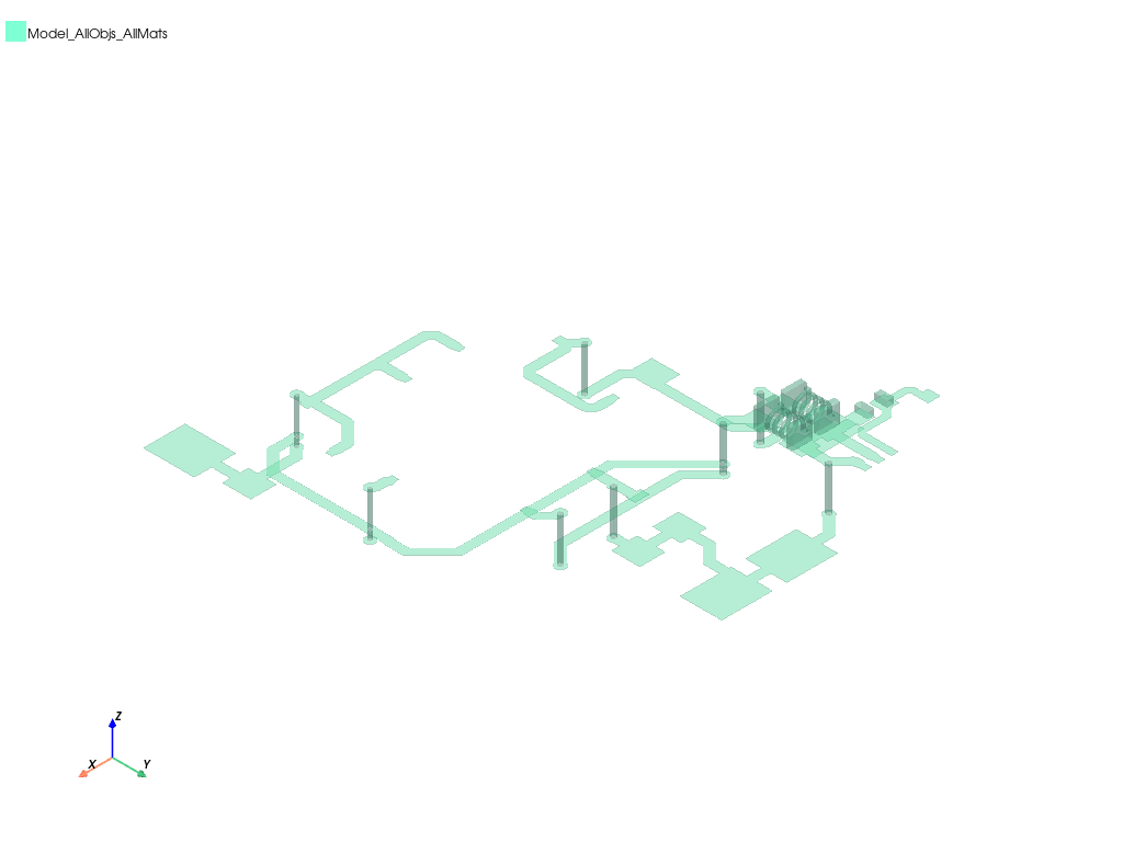
q3d.plot(assignment=objs_copper_names, show=False, output_file=os.path.join(q3d.working_directory, "Q3D.jpg"),
         plot_as_separate_objects=False, plot_air_objects=False)

<pyaedt.generic.plot.ModelPlotter object at 0x0000018804C408B0>
Assign source and sink#
Use previously calculated positions to identify faces, select the net “1_Top” and assign sources and sinks on nets.
sink_f = q3d.modeler.create_circle(q3d.PLANE.XY, location_u11_scl, 0.1)
source_f1 = q3d.modeler.create_circle(q3d.PLANE.XY, location_u9_1_scl, 0.1)
source_f2 = q3d.modeler.create_circle(q3d.PLANE.XY, location_u9_2_scl, 0.1)
source_f3= q3d.modeler.create_circle(q3d.PLANE.XY, location_u11_r106, 0.1)
sources_objs = [source_f1, source_f2, source_f3]
q3d.auto_identify_nets()

identified_net = q3d.nets[0]

q3d.sink(sink_f, net_name=identified_net)

source1 = q3d.source(source_f1, net_name=identified_net)

source2 = q3d.source(source_f2, net_name=identified_net)
source3 = q3d.source(source_f3, net_name=identified_net)
sources_bounds = [source1, source2, source3]

q3d.edit_sources(dcrl={"{}:{}".format(source1.props["Net"], source1.name): "-1.0A",
                       "{}:{}".format(source2.props["Net"], source2.name): "-1.0A",
                       "{}:{}".format(source2.props["Net"], source3.name): "-1.0A"})
True
Create setup#
Create a setup and a frequency sweep from DC to 2GHz. Analyze project.
setup = q3d.create_setup()
setup.dc_enabled = True
setup.capacitance_enabled = False
setup.ac_rl_enabled = False
setup.props["SaveFields"] = True
setup.props["DC"]["Cond"]["MaxPass"]=3
setup.analyze()
Field Calculator#
We will create a named expression using field calculator.
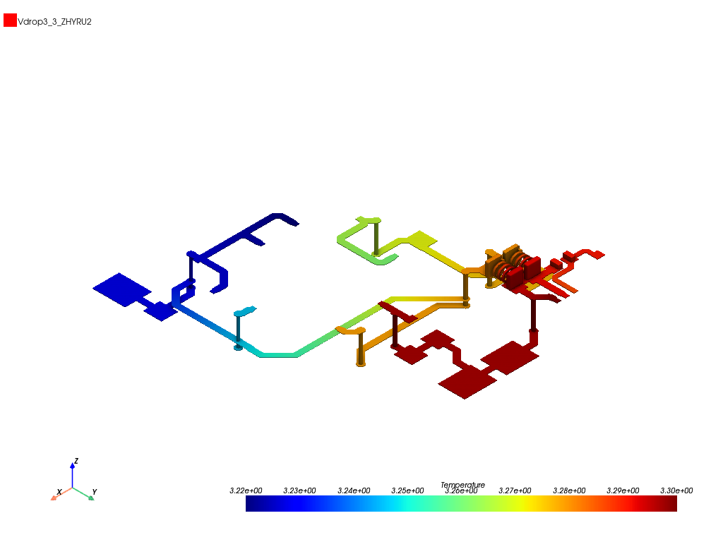
Phi plot#
Compute ACL solutions and plot them.
plot1 = q3d.post.create_fieldplot_surface(q3d.modeler.get_objects_by_material("copper"),
                                          quantity=drop_name,
                                          intrinsics={"Freq": "1GHz"})

q3d.post.plot_field_from_fieldplot(plot1.name, project_path=q3d.working_directory, mesh_plot=False, image_format="jpg",
                                   view="isometric", show=False, plot_cad_objs=False, log_scale=False)

<pyaedt.generic.plot.ModelPlotter object at 0x000001880A9F7A60>
Computing Voltage on Source Circles#
Using Field Calculator we can compute the voltage on source circles and get the value using get_solution_data method.
curves = []
for source_circle, source_bound in zip(sources_objs, sources_bounds):
    source_sheet_name = source_circle.name

    curves.append("V{}".format(source_bound.name))

    q3d.ofieldsreporter.CalcStack("clear")
    q3d.ofieldsreporter.CopyNamedExprToStack(drop_name)
    q3d.ofieldsreporter.EnterSurf(source_sheet_name)
    q3d.ofieldsreporter.CalcOp("Maximum")
    q3d.ofieldsreporter.AddNamedExpression("V{}".format(source_bound.name), "DC R/L Fields")


data = q3d.post.get_solution_data(
            curves,
            q3d.nominal_adaptive,
            variations={"Freq": "1GHz"},
            report_category="DC R/L Fields",
        )
for curve in curves:
    print(data.data_real(curve))
[3.260473193826186]
[3.2217855634697368]
[3.286373317438545]
Close AEDT#
After the simulation completes, you can close AEDT or release it using the
release_desktop method. All methods provide for saving projects before closing.
q3d.save_project()
q3d.release_desktop()
True
Total running time of the script: (6 minutes 17.995 seconds)