Note
Go to the end to download the full example code.
2D Extractor: stripline analysis#
This example shows how you can use PyAEDT to create a differential stripline design in 2D Extractor and run a simulation.
Perform required imports#
Perform required imports.
import os
import pyaedt
Set AEDT version#
Set AEDT version.
aedt_version = "2024.1"
Set non-graphical mode#
Set non-graphical mode.
You can set non_graphical either to True or False.
non_graphical = False
project_path = pyaedt.generate_unique_project_name()
Launch AEDT and 2D Extractor#
Launch AEDT 2023 R2 in graphical mode and launch 2D Extractor. This example uses SI units.
q = pyaedt.Q2d(project=project_path,
               design="differential_stripline",
               version=aedt_version,
               non_graphical=non_graphical,
               new_desktop=True
               )
C:\actions-runner\_work\_tool\Python\3.10.9\x64\lib\subprocess.py:1072: ResourceWarning: subprocess 11000 is still running
  _warn("subprocess %s is still running" % self.pid,
C:\actions-runner\_work\pyaedt\pyaedt\.venv\lib\site-packages\pyaedt\generic\settings.py:428: ResourceWarning: unclosed file <_io.TextIOWrapper name='D:\\Temp\\pyaedt_ansys.log' mode='a' encoding='cp1252'>
  self._logger = val
Define variables#
Define variables.
e_factor = "e_factor"
sig_w = "sig_bot_w"
sig_gap = "sig_gap"
co_gnd_w = "gnd_w"
clearance = "clearance"
cond_h = "cond_h"
core_h = "core_h"
pp_h = "pp_h"

for var_name, var_value in {
    "e_factor": "2",
    "sig_bot_w": "150um",
    "sig_gap": "150um",
    "gnd_w": "500um",
    "clearance": "150um",
    "cond_h": "17um",
    "core_h": "150um",
    "pp_h": "150um",

}.items():
    q[var_name] = var_value

delta_w_half = "({0}/{1})".format(cond_h, e_factor)
sig_top_w = "({1}-{0}*2)".format(delta_w_half, sig_w)
co_gnd_top_w = "({1}-{0}*2)".format(delta_w_half, co_gnd_w)
model_w = "{}*2+{}*2+{}*2+{}".format(co_gnd_w, clearance, sig_w, sig_gap)
Create primitives#
Create primitives and define the layer heights.
layer_1_lh = 0
layer_1_uh = cond_h
layer_2_lh = layer_1_uh + "+" + core_h
layer_2_uh = layer_2_lh + "+" + cond_h
layer_3_lh = layer_2_uh + "+" + pp_h
layer_3_uh = layer_3_lh + "+" + cond_h
Create positive signal#
Create a positive signal.
base_line_obj = q.modeler.create_polyline([[0, layer_2_lh, 0], [sig_w, layer_2_lh, 0]], name="signal_p")
top_line_obj = q.modeler.create_polyline([[0, layer_2_uh, 0], [sig_top_w, layer_2_uh, 0]])
q.modeler.move([top_line_obj], [delta_w_half, 0, 0])
q.modeler.connect([base_line_obj, top_line_obj])
q.modeler.move([base_line_obj], ["{}+{}".format(co_gnd_w, clearance), 0, 0])

# Create negative signal
# ~~~~~~~~~~~~~~~~~~~~~~
# Create a negative signal.

base_line_obj = q.modeler.create_polyline(points=[[0, layer_2_lh, 0], [sig_w, layer_2_lh, 0]], name="signal_n")
top_line_obj = q.modeler.create_polyline(points=[[0, layer_2_uh, 0], [sig_top_w, layer_2_uh, 0]])
q.modeler.move(assignment=[top_line_obj], vector=[delta_w_half, 0, 0])
q.modeler.connect([base_line_obj, top_line_obj])
q.modeler.move(assignment=[base_line_obj], vector=["{}+{}+{}+{}".format(co_gnd_w, clearance, sig_w, sig_gap), 0, 0])
True
Create coplanar ground#
Create a coplanar ground.
base_line_obj = q.modeler.create_polyline(points=[[0, layer_2_lh, 0], [co_gnd_w, layer_2_lh, 0]], name="co_gnd_left")
top_line_obj = q.modeler.create_polyline(points=[[0, layer_2_uh, 0], [co_gnd_top_w, layer_2_uh, 0]])
q.modeler.move([top_line_obj], [delta_w_half, 0, 0])
q.modeler.connect([base_line_obj, top_line_obj])

base_line_obj = q.modeler.create_polyline(points=[[0, layer_2_lh, 0], [co_gnd_w, layer_2_lh, 0]], name="co_gnd_right")
top_line_obj = q.modeler.create_polyline(points=[[0, layer_2_uh, 0], [co_gnd_top_w, layer_2_uh, 0]])
q.modeler.move(assignment=[top_line_obj], vector=[delta_w_half, 0, 0])
q.modeler.connect([base_line_obj, top_line_obj])
q.modeler.move(assignment=[base_line_obj], vector=["{}+{}*2+{}*2+{}".format(co_gnd_w, clearance, sig_w, sig_gap), 0, 0])
True
Create reference ground plane#
Create a reference ground plane.
q.modeler.create_rectangle(origin=[0, layer_1_lh, 0], sizes=[model_w, cond_h], name="ref_gnd_u")
q.modeler.create_rectangle(origin=[0, layer_3_lh, 0], sizes=[model_w, cond_h], name="ref_gnd_l")
<pyaedt.modeler.cad.object3d.Object3d object at 0x00000188077E3E80>
Create dielectric#
Create a dielectric.
q.modeler.create_rectangle(
    origin=[0, layer_1_uh, 0], sizes=[model_w, core_h], name="Core", material="FR4_epoxy"
)
q.modeler.create_rectangle(
    origin=[0, layer_2_uh, 0], sizes=[model_w, pp_h], name="Prepreg", material="FR4_epoxy"
)
q.modeler.create_rectangle(
    origin=[0, layer_2_lh, 0], sizes=[model_w, cond_h], name="Filling", material="FR4_epoxy"
)
<pyaedt.modeler.cad.object3d.Object3d object at 0x00000188077E1C30>
Assign conductors#
Assign conductors to the signal.
obj = q.modeler.get_object_from_name("signal_p")
q.assign_single_conductor(assignment=[obj], name=obj.name, conductor_type="SignalLine", solve_option="SolveOnBoundary",
                          units="mm")

obj = q.modeler.get_object_from_name("signal_n")
q.assign_single_conductor(assignment=[obj], name=obj.name, conductor_type="SignalLine", solve_option="SolveOnBoundary",
                          units="mm")
<pyaedt.modules.Boundary.BoundaryObject object at 0x00000188077E3B50>
Create reference ground#
Create a reference ground.
obj = [q.modeler.get_object_from_name(i) for i in ["co_gnd_left", "co_gnd_right", "ref_gnd_u", "ref_gnd_l"]]
q.assign_single_conductor(assignment=obj, name="gnd", conductor_type="ReferenceGround", solve_option="SolveOnBoundary",
                          units="mm")
<pyaedt.modules.Boundary.BoundaryObject object at 0x00000188077E0EE0>
Assign Huray model on signals#
Assign the Huray model on the signals.
obj = q.modeler.get_object_from_name("signal_p")
q.assign_huray_finitecond_to_edges(obj.edges, radius="0.5um", ratio=3, name="b_" + obj.name)

obj = q.modeler.get_object_from_name("signal_n")
q.assign_huray_finitecond_to_edges(obj.edges, radius="0.5um", ratio=3, name="b_" + obj.name)
<pyaedt.modules.Boundary.BoundaryObject object at 0x000001880ADA9540>
Define differential pair#
Define the differential pair.
matrix = q.insert_reduced_matrix(operation_name=q.MATRIXOPERATIONS.DiffPair, assignment=["signal_p", "signal_n"],
                                 reduced_matrix="diff_pair")
Create setup, analyze, and plot#
Create a setup, analyze, and plot solution data.
# Create a setup.
setup = q.create_setup(name="new_setup")
# Add a sweep.
sweep = setup.add_sweep(name="sweep1", sweep_type="Discrete")
sweep.props["RangeType"] = "LinearStep"
sweep.props["RangeStart"] = "1GHz"
sweep.props["RangeStep"] = "100MHz"
sweep.props["RangeEnd"] = "5GHz"
sweep.props["SaveFields"] = False
sweep.props["SaveRadFields"] = False
sweep.props["Type"] = "Interpolating"
sweep.update()
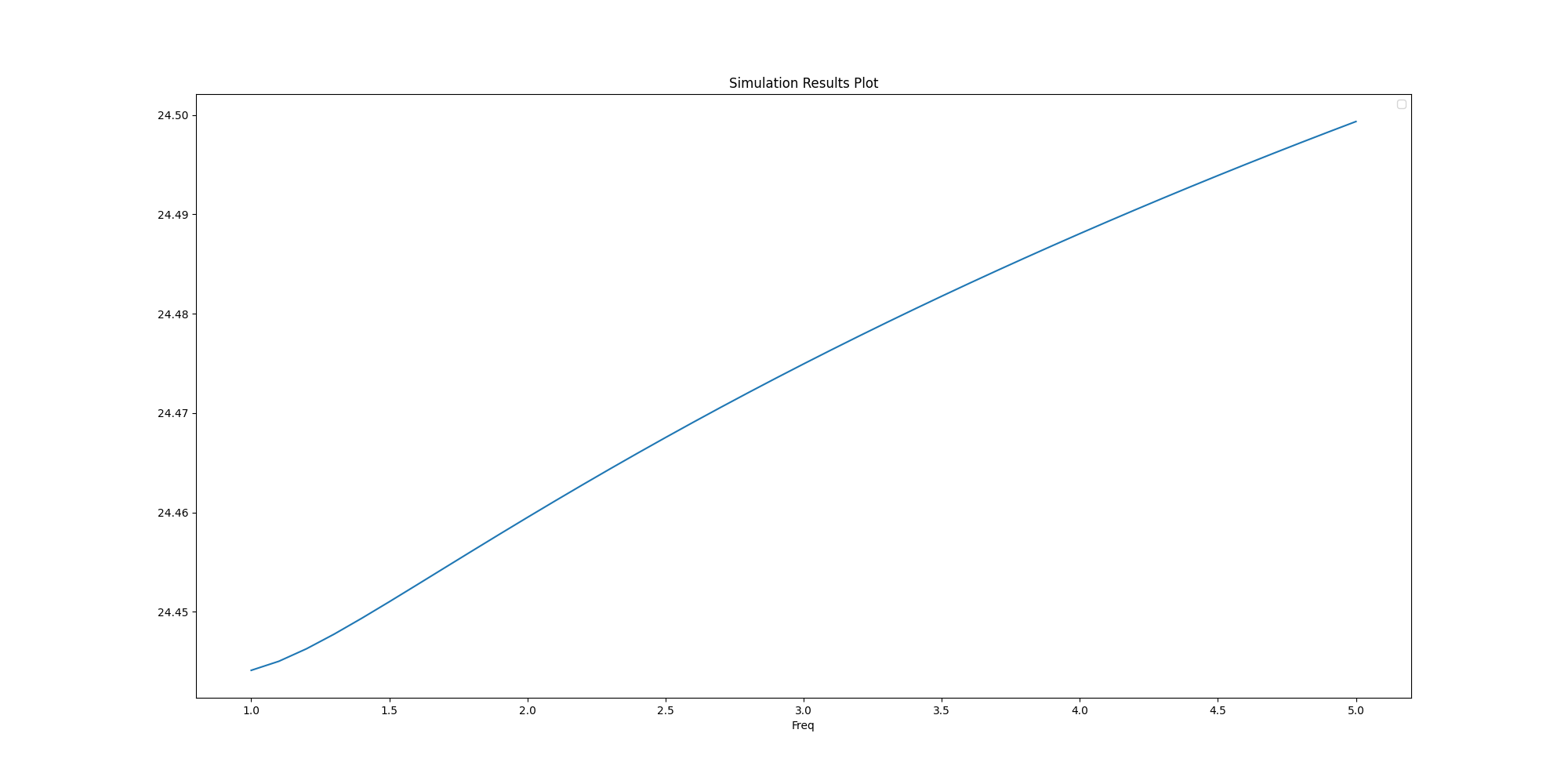
# Analyze the nominal design and plot characteristic impedance.
q.analyze()
plot_sources = matrix.get_sources_for_plot(category="Z0")
a = q.post.get_solution_data(expressions=plot_sources, context=matrix.name)
a.plot(snapshot_path=os.path.join(q.working_directory, "plot.jpg")) # Save plot as jpg
# Add a parametric sweep and analyze.
parametric = q.parametrics.add(variable="sig_bot_w", start_point=75, end_point=100, step=5, variation_type="LinearStep")
parametric.add_variation(sweep_variable="sig_gap", start_point="100um", end_point="200um", step=5,
variation_type="LinearCount")
q.analyze_setup(name=parametric.name)
True
Save project and release AEDT#
Save the project and release AEDT.
q.save_project()
q.release_desktop()
True
Total running time of the script: (3 minutes 34.727 seconds)