Note
Go to the end to download the full example code
Circuit: schematic creation and analysis#
This example shows how you can use PyAEDT to create a circuit design and run a Nexxim time-domain simulation.
Perform required imports#
Perform required imports.
# sphinx_gallery_thumbnail_path = 'Resources/circuit.png'

import pyaedt
import os
Launch AEDT#
Launch AEDT 2023 R2 in graphical mode. This example uses SI units.
desktop_version = "2023.2"
Set non-graphical mode#
Set non-graphical mode.
You can set non_graphical either to True or False.
The Boolean parameter new_thread defines whether to create a new instance
of AEDT or try to connect to an existing instance of it.
non_graphical = False
new_thread = True
Launch AEDT and Circuit#
Launch AEDT and Circuit. The pyaedt.Desktop class initializes AEDT and
starts the specified version in the specified mode.
desktop = pyaedt.launch_desktop(desktop_version, non_graphical, new_thread)
aedt_app = pyaedt.Circuit(projectname=pyaedt.generate_unique_project_name())
aedt_app.modeler.schematic.schematic_units = "mil"
Initializing new desktop!
Returning found desktop with PID 9076!
Create circuit setup#
Create and customize an LNA (linear network analysis) setup.
setup1 = aedt_app.create_setup("MyLNA")
setup1.props["SweepDefinition"]["Data"] = "LINC 0GHz 4GHz 10001"
Create components#
Create components, such as an inductor, resistor, and capacitor.
inductor = aedt_app.modeler.schematic.create_inductor(compname="L1", value=1e-9, location=[0, 0])
resistor = aedt_app.modeler.schematic.create_resistor(compname="R1", value=50, location=[500, 0])
capacitor = aedt_app.modeler.schematic.create_capacitor(compname="C1", value=1e-12, location=[1000, 0])
Get all pins#
Get all pins of a specified component.
pins_resistor = resistor.pins
Create port and ground#
Create a port and a ground, which are needed for the circuit analysis.
port = aedt_app.modeler.components.create_interface_port(name="myport", location=[-200, 0] )
gnd = aedt_app.modeler.components.create_gnd(location=[1200, -100])
Connect components#
Connect components with wires.
port.pins[0].connect_to_component(component_pin=inductor.pins[0], use_wire=True)
inductor.pins[1].connect_to_component(component_pin=resistor.pins[1], use_wire=True)
resistor.pins[0].connect_to_component(component_pin=capacitor.pins[0], use_wire=True)
capacitor.pins[1].connect_to_component(component_pin=gnd.pins[0], use_wire=True)
True
Create transient setup#
Create a transient setup.
setup2 = aedt_app.create_setup(setupname="MyTransient", setuptype=aedt_app.SETUPS.NexximTransient)
setup2.props["TransientData"] = ["0.01ns", "200ns"]
setup3 = aedt_app.create_setup(setupname="MyDC", setuptype=aedt_app.SETUPS.NexximDC)
Solve transient setup#
Solve the transient setup.
aedt_app.analyze_setup("MyLNA")
aedt_app.export_fullwave_spice()
'D:/Temp/pyaedt_prj_J4J/Project_9MZ.pyaedt\\Circuit_Design_B01\\Circuit Design_B01.sp'
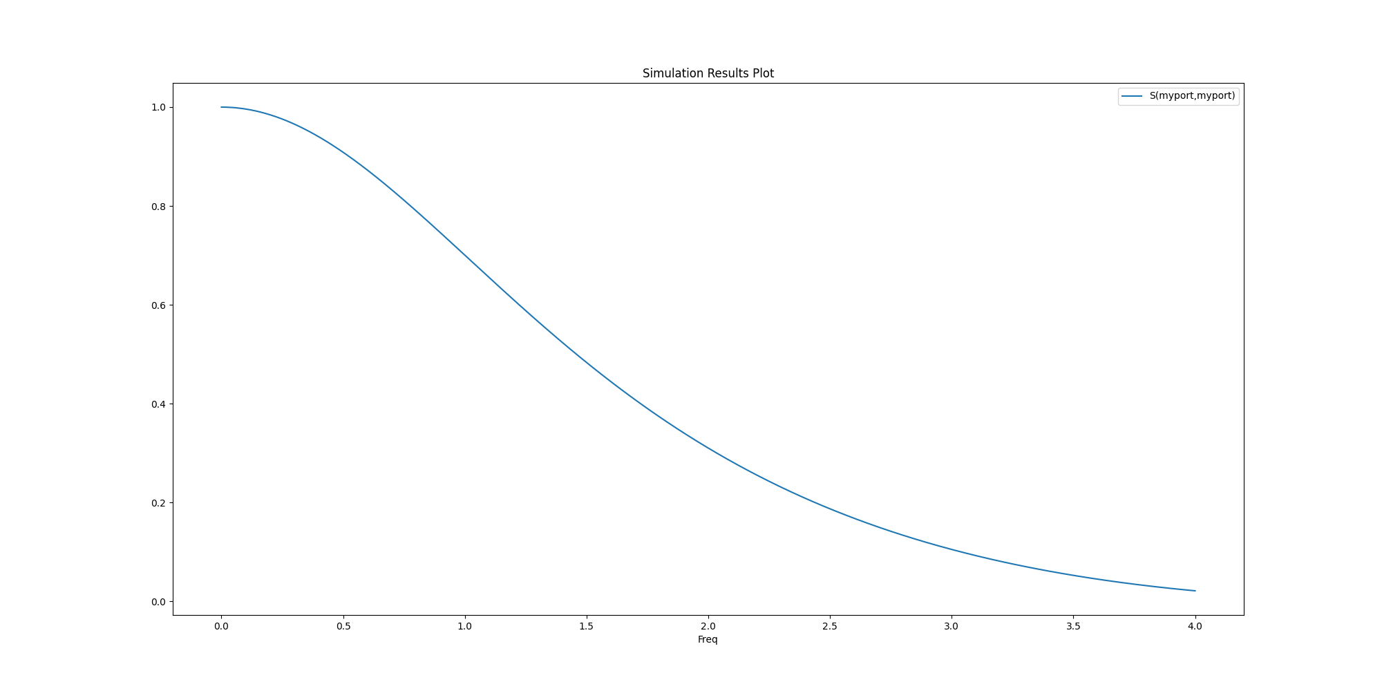
Create report#
Create a report that plots solution data.
        S(myport,myport)
0.0000          1.000000
0.0004          1.000000
0.0008          1.000000
0.0012          0.999999
0.0016          0.999999
...                  ...
3.9984          0.021101
3.9988          0.021083
3.9992          0.021065
3.9996          0.021046
4.0000          0.021028

[10001 rows x 1 columns]
Plot data#
Create a plot based on solution data.
fig = solutions.plot()
Close AEDT#
After the simulation completes, you can close AEDT or release it using the
pyaedt.Desktop.force_close_desktop() method.
All methods provide for saving the project before closing.
desktop.release_desktop()
True
Total running time of the script: (0 minutes 51.879 seconds)