Note
Go to the end to download the full example code.
Twin Builder: wiring a rectifier with a capacitor filter#
This example shows how you can use PyAEDT to create a Twin Builder design and run a Twin Builder time-domain simulation.
Perform required imports#
Perform required imports.
import math
import matplotlib.pyplot as plt
import pyaedt
Set AEDT version#
Set AEDT version.
aedt_version = "2024.1"
Select version and set launch options#
Select the Twin Builder version and set the launch options. The following code launches Twin Builder in graphical mode.
You can change the Boolean parameter non_graphical to True to launch
Twin Builder in non-graphical mode. You can also change the Boolean parameter
new_thread to False to launch Twin Builder in an existing AEDT session
if one is running.
non_graphical = False
new_thread = True
Launch Twin Builder#
Launch Twin Builder using an implicit declaration and add a new design with a default setup.
tb = pyaedt.TwinBuilder(project=pyaedt.generate_unique_project_name(),
                        version=aedt_version,
                        non_graphical=non_graphical,
                        new_desktop=new_thread
                        )
C:\actions-runner\_work\_tool\Python\3.10.9\x64\lib\subprocess.py:1072: ResourceWarning: subprocess 9492 is still running
  _warn("subprocess %s is still running" % self.pid,
C:\actions-runner\_work\pyaedt\pyaedt\.venv\lib\site-packages\pyaedt\generic\settings.py:428: ResourceWarning: unclosed file <_io.TextIOWrapper name='D:\\Temp\\pyaedt_ansys.log' mode='a' encoding='cp1252'>
  self._logger = val
Create components for bridge rectifier#
Create components for a bridge rectifier with a capacitor filter.
# Define the grid distance for ease in calculations.

G = 0.00254

# Create an AC sinosoidal source component.

source = tb.modeler.schematic.create_voltage_source("V_AC", "ESINE", 100, 50, [-1 * G, 0])

# Create the four diodes of the bridge rectifier.

diode1 = tb.modeler.schematic.create_diode(location=[10 * G, 6 * G], angle=270)
diode2 = tb.modeler.schematic.create_diode(location=[20 * G, 6 * G], angle=270)
diode3 = tb.modeler.schematic.create_diode(location=[10 * G, -4 * G], angle=270)
diode4 = tb.modeler.schematic.create_diode(location=[20 * G, -4 * G], angle=270)

# Create a capacitor filter.

capacitor = tb.modeler.schematic.create_capacitor(value=1e-6, location=[29 * G, -10 * G])

# Create a load resistor.

resistor = tb.modeler.schematic.create_resistor(value=100000, location=[39 * G, -10 * G])

# Create a ground.

gnd = tb.modeler.components.create_gnd(location=[5 * G, -16 * G])
Connect components#
Connect components with wires.
# Wire the diode bridge.

tb.modeler.schematic.create_wire(points=[diode1.pins[0].location, diode3.pins[0].location])
tb.modeler.schematic.create_wire(points=[diode2.pins[1].location, diode4.pins[1].location])
tb.modeler.schematic.create_wire(points=[diode1.pins[1].location, diode2.pins[0].location])
tb.modeler.schematic.create_wire(points=[diode3.pins[1].location, diode4.pins[0].location])

# Wire the AC source.

tb.modeler.schematic.create_wire(points=[source.pins[1].location, [0, 10 * G], [15 * G, 10 * G], [15 * G, 5 * G]])
tb.modeler.schematic.create_wire(points=[source.pins[0].location, [0, -10 * G], [15 * G, -10 * G], [15 * G, -5 * G]])

# Wire the filter capacitor and load resistor.

tb.modeler.schematic.create_wire(points=[resistor.pins[0].location, [40 * G, 0], [22 * G, 0]])
tb.modeler.schematic.create_wire(points=[capacitor.pins[0].location, [30 * G, 0]])

# Wire the ground.

tb.modeler.schematic.create_wire(points=[resistor.pins[1].location, [40 * G, -15 * G], gnd.pins[0].location])
tb.modeler.schematic.create_wire(points=[capacitor.pins[1].location, [30 * G, -15 * G]])
tb.modeler.schematic.create_wire(points=[gnd.pins[0].location, [5 * G, 0], [8 * G, 0]])

# Zoom to fit the schematic
tb.modeler.zoom_to_fit()
Parametrize transient setup#
Parametrize the default transient setup by setting the end time.
tb.set_end_time("100ms")
True
Solve transient setup#
Solve the transient setup.
tb.analyze_setup("TR")
True
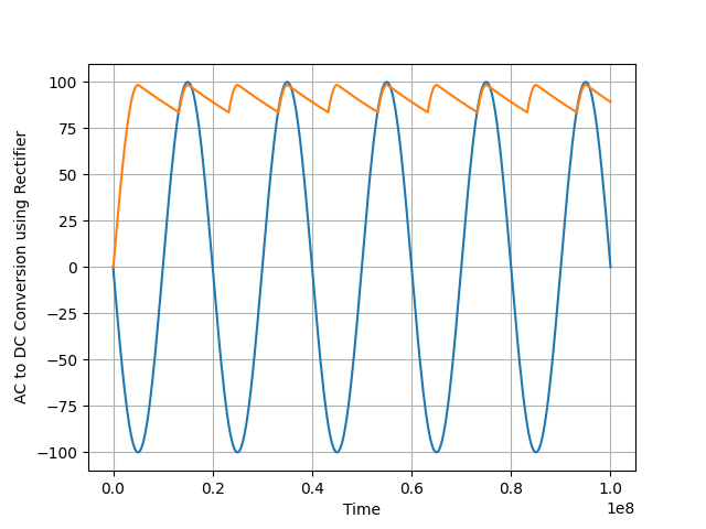
Get report data and plot using Matplotlib#
Get report data and plot it using Matplotlib. The following code gets and plots the values for the voltage on the pulse voltage source and the values for the voltage on the capacitor in the RC circuit.
E_Value = "V_AC.V"
x = tb.post.get_solution_data(E_Value, "TR", "Time")
plt.plot(x.intrinsics["Time"], x.data_real(E_Value))

R_Value = "R1.V"
x = tb.post.get_solution_data(R_Value, "TR", "Time")
plt.plot(x.intrinsics["Time"], x.data_real(R_Value))

plt.grid()
plt.xlabel("Time")
plt.ylabel("AC to DC Conversion using Rectifier")
plt.show()
C:\actions-runner\_work\pyaedt\pyaedt\.venv\lib\site-packages\pandas\core\arraylike.py:399: RuntimeWarning: invalid value encountered in sqrt
  result = getattr(ufunc, method)(*inputs, **kwargs)
C:\actions-runner\_work\pyaedt\pyaedt\.venv\lib\site-packages\pandas\core\arraylike.py:399: RuntimeWarning: invalid value encountered in sqrt
  result = getattr(ufunc, method)(*inputs, **kwargs)
Close Twin Builder#
After the simulation is completed, you can close Twin Builder or release it. All methods provide for saving the project before closing.
tb.release_desktop()
True
Total running time of the script: (0 minutes 33.676 seconds)